Exhaust Systems
The factory Indian "Two-Into-One" system is actually a pretty well designed system. They have a mellow, and unique sound. Contrary to common beliefs, dual pipes on V-Twins don't work! Dual pipes kill torque, and torque is what we are trying to find. Indian was overly generous with their pipe sizes, especially for the Scout. Chiefs, and Scouts use 1 5/8" OD pipe throughout their systems. Their mufflers have been OK for flow, but for bobbers, omitting the muffler with a straight section of 1 5/8" pipe will make even better flow, better resonance, and sound a bit hotter. I think it's a good look as well. Every front manifold for Indians suffer a severe problem. When the pipes are assembled, they drill a small hole in the front down pipe where the rear down pipe will weld to it. This becomes a point of high restriction. You often see severe pipe-blueing at this intersection. It can usually be opened up by about twice the size by cuttung out a 1" access hole directly under the intersection of the rear pipe to the front pipe. You can work through the 1" hole with die grinders, and a 3/8" metal burr to grind away the material of the front pipe to create a smooth opening for the rear down pipe. You will gain alot of power, and the rear cylinder will run cooler! Vincents suffer from the same problem. When finished grinding, make a 1" curved disc to heli-arc weld back in there. Touch it up with a bit of silver spray paint, and you have a much better pipe.
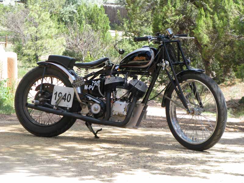
I have a dyno with an "air/fuel" sniffer, and I use it alot to test performance modifications. I did a long study on Indian exhaust systems on the Scout Land Speed racer pictured below. The first time I crewed for this bike, he had a long 2-into-1 straight pipe. I thought that "Duals" would be better. At Bonneville we were making some consistant runs on the 2-into-1, and switched over to the duals. We lost 10 MPH! After going back to the 2-into-1's we picked our speeds back up. I decided to do a comprehensive test. I made tail-pipe sections in 6" lengths that I could stack together to play with lengths. We used basically a stock front header (1 5/8" OD), with a 1 5/8" straight tail-pipe. I tried (4) different lengths. The shortest was about 6" further than the rear of the front header. It made a little more peak power, but suffered alot of torque. The longest tail-pipe made the most torque, and lost only a little peak power. The longest tail-pipe made a very broad torque curve. This pipe came all the way back to the rear of the rear tire. As I shortened the tail-pipe, I found the peak power pick up a little more power, without losing much torque. The best power combo for our needs was found with the tail-pipe ending 6" from the rear of the rear tire.
Tail-pipe ends are another controversial subject. A straight cut-off end is supposed to be the worst choice. It is supposed to disrupt resonance. Harley-Davidson found on their Daytona KR-TT racers that a slash cut helped to broaden the torque curve. It should be a longer taper, like 30 degrees. A megaphone is the best choice, but there is either alot of science, or trial and error needed. The best type of megaphone is a triple angled megaphone, first with a long slow taper, then a short section of wider taper, and a reversal using the same sharper taper, ending in an opening that is about double the area of the tail-pipe section area. On a Norton 873 land Speed racer, I tried (3) different length megaphones with the same exit cone configuration. The middle lengthed megaphone made exactly (4) more horsepower (rear wheel) than the other (2)!
Now for those who want to crunch numbers. There have been some formulas used for calculating proper pipe sizes, and lengths that I have found to be reliable. They assume a target exhaust gas speed of 300 feet/second. At 300 ft/sec, the gases carry the most enertia at the lowest amount of drag. This enertia is the force that helps extract the gases from the pipe, as well as to help to draw in the next intake charge. This gas speed is achieved throught the correct pipe size, while the overall pipe length is determined more by a target RPM where the best power is desired. While the exhaust gases are traveling down the pipe, there is a wave reflex pulse moving back and forth within the pipe based on RPM. This wave pulse can be timed, by proper length, so that when the exhaust valve opens, there is a wave suction acting on the opened combustion chamber to help extract burnt gases, and draw in a new clean intake charge. These formulas are looking for peak power at specific RPM's where the motor will be used. This is usually a narrow RPM range. Therefore, they are a starting point to build from. So, a correct length shorter pipe will yield the best peak power over a narrow RPM range, while a longer pipe will lose a small amount of power, while increasing, and broadening the torque.
The formula for pipe length uses an exhaust gas wave velocity of 1,700 ft/sec. (based on best pipe diameter for 300 ft/sec gas speeds) multiplied by 120 to equal 204,000. Divide this by the target RPM for peak power. For a 58" Scout, or 74" Chief the peak RPM will be around 5,000 RPM. For a 45" Scout the peak RPM would be around 6,000 RPM. Using these numbers, the best length for a 45" Scout is 34", and 40.8" for a 58" Scout, or 74" Chief. This length can be halved, or doubled, and the wave reflex will reverse at the exhaust valve at the correct time of valve opening to extract gases properly (assuming the correct pipe diameter).
The formula for pipe diameter is more complex. It takes into account piston speeds, based on stroke. The target exhaust gas speed of 300 ft/sec is found by using piston speed (based on stroke) divided by 60, then multilpied by the piston bore size "squared", that is divided by the pipe size ID "squared". The pipe size is the variable that can be adjusted to try and achieve the target speed of 300 ft/sec. Velocity (300)=(piston speed / 60) X (Piston Bore "Squared" / Pipe ID "Squared"). Piston Speed is the stroke times (2), divided by 12, times the RPM for peak power. For a 45" Scout, the piston speed is: 3.5" stroke X 2 = 7", divided by 12 = .58333. Multiply this by the target RPM of 6,000 = 3,500 ft/min mean piston speed. Divide this by 60 = 58.333 ft/sec. Now, Square the bore of 2.875" to equal 8.265 divided by the pipe ID squared (use 1.25" ID for 1 3/8 OD pipe) = 1.5625, = 5.2896. Then, 58.333 X 5.2896 = 308.558. Therefore, the correct pipe size for a full race 45" Scout would be 1 3/8" OD pipe. I have found good results using this pipe size! Without doing the math, a 58" Scout at 5,300 RPM would be at 285.69 ft/sec gas speed using 1 1/2" OD pipe. I know that a max performance 58" Scout like my Twin-Scout motors want to rev up to around 5,300 RPM max under load at high speed.
Another new trend for performance pipes is to step them. "Stepping", means to use a smaller pipe from the exhaust port for about 8"-10", and then step up the pipe size to the next size by slipping the bigger pipe over the smaller pipe, and welding it. This helps to turn the wave reflex pulses back around without entering the combustion chamber. I like to keep the factory exhaust port size stock, but smooth the surface. Then at the port exit, I bevel it larger in the last 1" of length. I bevel it to the desired pipe size. I then make special nipples that go over the outside of the port, but step down to the new smaller pipe size . I stepped my pipes on the Twin-Scout, but I used one size larger for the beginning, and ending sizes, because I run Nitrous-Oxide, with additional fuel. This makes the motor think it is actually much larger, which would require a step up in pipe size.
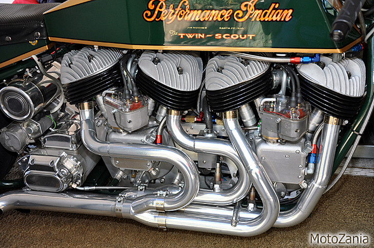
In the picture above of my Twin-Scout, I used a stepped-up tail-pipe with similar pipe length of a header pipe. This accomodates the flow of two cylinders, and carries a double wave pulse. They work well! You can see that I am using ceramic-aluminum pipe coating from "Performance Coatings" in Oregan. They coat the inside as well, which keeps the exhaust gas temps higher to increase the exhaust gas enertia. The pipes are cool to the touch after about 1 minute from killing the motor! It works!
Drag Pipes are a "Drag"!
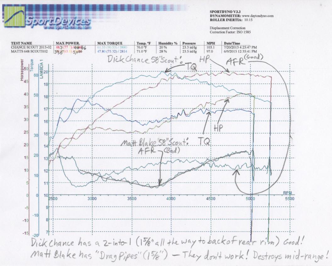
I built (2) 58" Scout "Stroker" performance motors for (2) of my friends. One has "648" Big Base cases, while the other was stock Sport Scout cases. I used the same cams and lifters in each (my racing lifters, and my Street and Strip) cams. They had the same pop-up "Arias" forged pistons, and the same porting. They both used the same Mikuni VM36 carbs, and magnetos. The only difference was in the pipe setup. Dick Chance's LSR bike used a "2-into-1" system using the stock front header (with the rear pipe weld joint cleaned out for better breathing). I extended a 1 5/8" tail-pipe all the way back to the rear tire. It ended with a slash-cut end. Matt Blake chose to use Bob Stark's chromed "Drag Pipes" (what a drag!). The dyno chart below shows both bikes best dyno runs shown together, so you can see the power difference. At mid range, the drag pipe's power fell off to roughly 1/2 of the power from the "2-into-1" system. You can clearly see that at just over 3,500 RPM, Matt's motor has lost "half" of it's power. They make the same power at low RPM, and less power at high RPM, but the mid-range is destroyed! The reason is because the pipe's wave reflex action is all wrong due to the short pipe lengths. That happens at 60-65 MPH, where you are looking for power to pass, or good power for having some fun. Note: Dick Chance's bike has real high gearing for Bonneville, and if it had the same as Matt's street bike, then Dick's bike would show even more power on this dyno chart! Take a look at the dyno chart below. All the data is there.
CONTACT INFORMATION:
James R. Mosher
(505) 466-7870