Indian Valve Train Design Revealed
The following study is a result of a year's research to get a full understanding of the design elements of the Indian "Single Cam Lobe per Cylinder/Finger Follower Lifter System". I persued this research in order to be able to correctly manufacture new Scout racing cams, and lifters for my Twin Enginned Scout Bonneville racer, as well as to be able to provide a small batch of racing designed cams, and lifters to the racing community, as well as the serious Scout Bobber builder.
The results of my research led me to design a new model Scout lifter with correct geometry based on todays racing cam technology. I have also designed (5) new cam profiles for racing, as well as "Street and Strip" use. See my racing cam page for details, and costs.
Until now, the Scout racer/builder has had virtually no options for cams, or lifters. There were the standard Sport Scout cams, and lifters with very poor performance potential, and most found today are worn out. Then there is the Scout Bonneville cams, and lifters, which are very rare, and also worn out (as well as very expensive). Actually the Scout Bonneville cams, and lifters were not a very good design, and I will explain why they should be avoided. See my page on "Avoiding Scout Bonneville cams, and lifters".
Indian Valve Train Layout Description
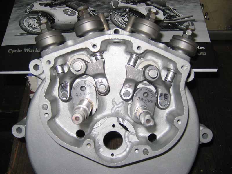
Here is a Late Scout cam case with my new racing lifter, and (2) prototype cam lobes shown without the gears for clarity.
The Indian cam chest is composed of first, a center low mounted 20 tooth pinion gear that rotates clockwise to turn the front cylinder cam counter-clpckwise. The front cam, in turn, turns the rear cylinder cam clockwise. The front cam in magneto equipped models also turns a pair of gears to drive the magneto. The rear cam is slightly elevated above the pinion gear, and thus, the rear push rods are slightly shorter than the front push rods in length. Looking at the motor from the right side, you can see that the function of the front cylinder is a direct mirror image of the rear cylinder. Therefore the cams need to rotate in opposite directions. Each cam rotates, and first comes into contact with the exhaust lifter, and before it is finished, it comes in contact with the intake lifter. The period when the exhaust lifter is not yet closed, and the intake is already opening is called the "Overlap Phase". Long duration cams will usually increase this overlap period significantly compared to a low performance cam. The negative side of large overlap duration is a lower intake vacuum at lower RPM creating a loss of some low-end torque. The positive side of long overlap duration is a significant gain in power at mid to upper RPM due to the inertia of air/fuel mixture helping to fill the cylinders, while also helping to extract the exhaust better. There is a whole science to building intake runners, and exhaust systems to optimize these functions.
There are (4) seperate lifters, one per valve, and there are (2) pivot pins for the lifter pairs to rotate on. One intake, and exhaust per cylinder. The lifters sit on the pins side to side. The intake lifters go on first (closer to the flywheels). There are (4) push rod guides pressed into the case above the lifters, and the push rods contact the lifters at an angle that is different than the centerline of the cam-shaft, and the lifter pivot pin. More on this later. Each cam is made up of a 40 tooth cam gear with the cam lobe mounted to the back side. The cam/gear is pressed onto a cam shaft, and the shaft rides on (2) bushings (one in the engine case, and the other in the cam cover). The front shaft has a spiral grooved end to drive the oil pump feed, and the rear shaft is keyed, and threaded for a gear to drive the oil pump return, and the distributor. The rear cam/gear requires a key when installing it to the shaft. The whole assembly is fed oil from crankcase pressure forcing oil vapors in from some small holes.
The 7 elements of Indian Cam & Lifter Design.
There are 7 seperate design elements that need consideration when designing a proper cam, and lifter combination. Changing any one element requires an adjustment in all the other elements. These design elements are: 1) Lifter Push Rod Pad Location, 2) Pivot Pin to Roller Axle Center location, 3) Cam Lobe Base Circle Diameter, 4) Cam Lobe Shape, 5) Roller Diameter, 6) Cam Lobe Height/Max Lift, 7) Valve Spring Rate, and Pressures.
1) Lifter Push Rod Pad Location
As mentioned above, the push rods are not in the same plane as the center of the cam shaft and the lifter pivot pin. They are leaning outward to the front, or rear, although they are running parallel to each other. They are spaced 1 7/8" apart from each other, so they are shifted 15/16" to either side of the lifter pivot pin on a new axis. The push rod pad locations on the intake lifter is in a different spot from the exhaust lifter. The push rod pad on the exhaust lifter appears to be farther away from the pivot pin than on the intake lifters. This does not effect the rocker ratio, or lift curve function intake vs. exhaust. Keep in mind that both lifters will rotate back, and forth the same number of degrees as the cam lobe rolls by, and the ideal point of contact of the bottom of the push rod to the lifter pad should be at a 90 degree angle from the center of the push rod to the center of the lifter pivot pin when at 1/2 valve lift. This allows the lifter pad to rise, and fall the same amount from this 90 degrees from zero lift to maximum lift. This 90 degree intersection will offer the most efficient amount of lift, loading, and thus wear. As the lifter rotates back, and forth, the push rod needs to constantly be in contact with the arched lifter pad at the bottom of the push rod. There is a geometry that is critical here. The arched pad is ground with a 3/8" radius, with it's center found 15/16" from the lifter pivot pin center (in line with the (2) push rods), and 3/8" below the mid-lift 90 degree push rod to pad intersection. I have made a precise grinding jig for this function. When the pad is ground correctly, the push rod bottom is always in contact with the top of the arched radius, although the contact point moves inwards slightly at maximum, and minimum lifts. Indian incorrectly ground these pads, since you can often see crescent shaped grooves on the inside dished area of the pads from wear caused by the side edge of the push rod bearing into the lifter material. This will cause noise, and cam wear, because this bad push rod contact is happening at valve closing, where proper ramp operation is important for good valve closing action. I have extended my lifter pad arches inward to accept a wide variety of cam base circles, and lifts.
2) Lifter Pivot to Roller Axle Distance
The distance from the lifter's pivot pin to the lifter's roller axle center directly controls the function of cam lobe center location. This is the term "Lobe Centers". Lobe centers were not mentioned in cam desing untill sometime in the late '70's. It is of prime interest today in cam design. Each cam lobe action, both intake, and exhaust are measured from TDC (in the overlap phase) to the center of the cam lobes action. This is usually measured at .050" of valve lift (not lobe lift) off the cam's base circle after just opening, and just before closing. Using a degree wheel, and dial indicator on top of the valve, find the opening, and closing points (at .050"), and notice the number of degrees. Now bisect these degrees to find the mid-point. This is where the lobe centers are. It is accepted that mild cams should have lobe centers near 106 degrees, while performance cams will be more like 102 degrees. When both intake, and exhaust lobes are at the same lobe center number, the cam is considered "centered". A cam can then be either advanced, or retarded to change the power characteristics, and this is done by rotating the lobes a small number of degrees. Usually (2) degrees of advance will give a noticable increase in torque at a small loss of top end power. The term "degreeing a cam" means to get the cam lobe location just where you want it by carefully measuring everything, then making the appropriate adjustments. When installing seperate cam lobes onto ground-down cam/gears, I use special offset pins to install the lobes, which allows me to shift the lobe either way a precise amount. The distance from the pivot pin to the roller axle center on Indian standard lifters is very wide. This causes the lobe centers to be very long. The Chief standard lifter yields 115 degree lobe centers, while I have measured between 116 and 118.5 degree lobe centers in Scouts due to the variety of lobes from year to year. These are awful numbers, like those found in lawn mowers! On the other hand, the Indian factory attempted to make a high performance "Bonneville" version of cams, and lifters. On the Chief, they moved both intake, and exhaust rollers inward (shorter distance) the same amount by moving the roller 10 degrees of crank rotation. This now yields lobe centers of 105 degrees per cam lobe. This is a very good number considering the mild performance nature of the Chief Bonneville cam. It comes in very close to the same as a stock Harley-Davidson Evo motor in specifications. On the other hand, The Scout Bonneville lobe centers were changed in a very irresponsible way to get their results, but I won't cover it here. See my seperate page "Avoiding Scout Bonneville Cams, and Lifters" for exact details. Because the lifter swings an arc when it is operating, there is a slight relative lobe center change when comparing points near the base circle compared to at the top of the lobe. This can't be helped, but it can be minimized to less than one (1) degree of fluctuation by carefully picking the correct base circle diameter relative to the lift. See the next section.
3) Cam Lobe Base Circle Diameter
As mentioned above, the base circle diameter has a direct corrolation to the amount of lift in a cam design when trying to minimize the amount of lobe center variation from base circle through max lift. This is a very complicated situation, and I have a formula for calculating the correct base circle size to optimize a stable lobe center. This formula is proprietary, and I'm protecting it from those who would copy my cams, and lifters. Also, when designing for maximum lift, using a smaller base circle , and a taller lobe, a very high lift profile can be designed to fit within the design constraints of the cam case. It is still important to use my formula to balance the lift to base circle to maintain the best lobe center arc. I have designed a correct geometry cam lobe combination that yields .423" lift, for both intake, and exhaust. I feel this is the absolute maximum that will fit into the cam chest environment, without major work. Plus, .423" lift is about all the Scout combustion chamber can handle. The Bonneville Chief has .412" lift. Avoid using re-ground base circle cams that are re-ground standard cams to mimic Bonneville cams. They have very small base circles for the amount of lift, and they will have a widely swinging lobe center when operating, and the performance won't match that of an original Bonneville cam. Other issues arrise from smaller base circles. One is a possibility that the push rod adjusters will hit the top of the push rod guide before the lifter hits bottom towards zero lift, requiring longer push rods, and there is that problem of not having the push rod pads at the 90 degree point at mid lift, which will cause less than optimum valve lift and increased lifter pad wear. Plus the smaller the base circle, the slower the roller rotates on the base circle, and the resulting acceleration of the roller up the side of the lobe could cause the roller to skid some.
4) Cam Lobe Shape
There are many different cam lobe shapes out there, and there is no one best shape. A mild cam lobe with very little duration will look more pointed than one with alot of duration. A performance cam with alot of duration can have a lobe top that is as wide (or wider) than the base circle. Sometimes, they are even slightly squared off at the top, so that after a rapid opening, the max lift is reached, and continues through a large number of degrees before it starts to close. When designing a cam, several things should be considered. Do you want a cam that is going to wear out all the components prematurely, or do you want one that will cause valve float at high RPM? The correct answer the these questions should be NO! There is no simple rule to minimizing wear, and valve float, but any rapid changes in lift should be avoided. Cams that open abruptly are going to create tremendous wear, and cams that are too squared off at the top are likely to cause valve float. I have seen several old performance cams that are refered to as "Hooked Cams". They are assymetrical, meaning one lobe side does not resemble the other. I find this irresponsible, and incorrect, because since there are (2) lifters operating on the same cam lobe in a mirror image manor, a symetrical lobe would be best, because the action of the exhaust lifter will be repeated in reverse order with the intake lifter shortly after. If you try to optimize a cam/lifter action with an assymetrical lobe, you might help the exhaust function, but hurt the intake function in the process, etc. When considering the wear, and load issue, abrupt lift changes should also be avoided since the rollers can skid, and stop rolling, which causes rapid cam and roller wear. The cure is not to increase spring pressure, because it will just prematurely wear out the cam shaft bushings, and the roller axles. A good balance needs to be designed in for best performance, and long life. When designing a cam, you have to consider how the bike will be used. If it is an all out drag bike, you need alot of lift, and alot of duration (with it's resultant long overlap phase). This will make good power ONLY at very high RPM, with very poor, or no low end torque. It may need to idle at 2,000 RPM! To preserve a good amount of torque, you will want a good amount of duration, but not too much, and alot of lift, but also not too much. The lesser duration will yield a lesser overlap phase, which will make better vacuum at low speeds. A cam like this works best with a little advance (like 2-3 degrees), and alot of compression. With it's longer duration than stock, the intake valve will close later giving less actual compression at low speeds, so an increase in compression is in order for good low end, and the extra compression will make real good power at the higher RPM range as well. Increasing the lift alone has little effect on low end torque, while an increase in duration without an increase in compression creates a large drop in low end torque.
5) Roller Size
Stock Scout rollers are 5/8" diameter, and 1/4" wide running on a 5/16" axle. Chief rollers are 3/4" diameter, and 5/16" wide running on a 3/8" axle. Obviously the Scout rollers are more delicate, but their saving grace is the fact that the Chief, and the Scout have (2) very differnt rocker arm ratios. The Chief rocker ratio is .82:1 (.86:1 for Bonneville), and the Scout is at .65:1, therefore the Scout rollers suffer less pressure. Plus Chief valves are heavier at 2" valve heads, and 3/8" stems, while Scout valves are lighter with 1 3/4" valve heads, and 11/32" stems. Chiefs, and Scouts have always used the same valve springs, so the Scout should be fine at much higher RPM than the Chief. I have written alot about valve springs. See my "Valve Spring Study". Some racers have experimented by upsizing their Scout rollers from 5/8" to 3/4" diameter, and they claim quicker opening, and closing, and a lift curve that is more open at each end of the spectrum due to the point of contact on the lobe. This is complicated stuff, and usually will require hand-made lifters.
6) Lobe Height / Max Lift Relationship
I lightly touched on this above, but since there is a physical limit to the height of a cam lobe in the Scout cam chest, there is a limit to the max lift available. A tall lobe will swing, and hit the aluminum pinion bushing bosses in the case (which already have to be trimmed about .020" when using my .423" lift cams), and the rear cylinder exhaust lifter can hit the rear edge of the cam chest insides, as well as the bottom of the push rod guides. When using my .423" lift cams, you have to grind off the complete exposed portion of the bottom of the rear cylinder push rod guides right up to the case aluminum, or the lifter pads will hit them. Now knowing these space considerations, I can apply my base circle, to lobe height formula (maintaining optimum lobe center arc) to achieve the highest lift available at .423". That is a good number for lift for flat out racing, even with a 58" (955cc) stroker Scout. With that much lift, and my compression raised to the limit, I can play with the duration to try and preserve the needed torque to carry my Twin Enginned Scout Bonneville racer to very high speeds.
7) Valve Spring Rate, and Spring Loading
I can't give hard numbers here, because there are so many variables to consider, but I can speak in general terms. You should read my "Valve Spring Study" first. As mentioned before, it is best to design a cam with minimal component wear, and maximum power in mind, and while using the most appropriate valve spring. Installed springs are measured with a "Seat Pressure", and a "Full Open Pressure". The heavier the total mass of valve train components, the heavier the seat pressure should be. A stock Scout should typically be around 80 pounds on the seat, and at or above 160 pounds at max lift within the normal operating speed range. Now if you increase the max lift, the full open pressures will go up accordingly, which is needed to get the valve to properly close without valve float. Plus if the operating RPM is to be significantly increased, either the spring pressure needs to be greater than usual, or the valve train components need to be lightened. Springs of diffeent styles will have a different spring rate, which will either have a higher or lower full open pressure assuming they are both set at the same 80 pound seat pressure. Once an RPM limit, max lift, and valve train component weight has been determined, a proper spring pressure, and rate can be determined. This is next to impossible to predict precisely. Too tight causes excess wear, and a power loss, while too light causes valve float, and potential piston/valve damage in over head valve motors. On my Twin Enginned Stroker Scout for Bonneville, with very light Titanium valves, and retainers, I am using Gary Stark's new "7-Coil" springs shimmed up for a 105 pound seat pressure, and hope for a 180 pound full open pressure. With light valve train, I should be good for 7,500 RPM (I hope!). This RPM should only be rarely seen climbing through the gears, and ending with a 6,500 RPM top gear steady pull. There are several spring rate calculators to be found on the internet (happy surfing!)
CONTACT INFORMATION:
James R. Mosher
(505) 466-7870