Indian Heads - Chief & Scout
Milling Heads
Milling the heads is never a good idea! Most people mill material off the head gasket surface to reduce the net combustion chamber size, in order to raise compression. Compression is good, but there are better ways to get performance from increased compression. By milling the material off the head gasket surface, you have lowered the roof of the combustion chamber, to where it will flow less air/fuel mixture into the bores. It is a better idea to fill in the sides of the chambers, and to leave the chamber height as tall as possible. The factory offered "Bonneville" versions for both Chiefs, and Scouts. One of the Bonneville's features was a taller piston, that actually popped-up above the cylinder deck by about .100" height. The heads then needed to be "fly-cut" to make room for the piston top to go up above the deck. This fly-cut will actually open up the flow path into the bores a bit better than stock. A milled head can be "un-milled", so to speak, by using thicker copper head gaskets that can be custom made by "Cometic Gaskets". I have some stock, and modified patterns there for them to work with. A milled head will almost always cause the valve heads to hit the head surface, so some relieving will need to be done.
Filling instead of Milling
On my Scout racing projects, I have experimented with filling areas of the combustion chamber to raise compression, without reducing the heights of the combustion chamber. I have had good success doing this. On my Twin-Scout, which is both bored, and stroked to 1,010cc's per motor, I have been able to increase compression from stock 4.4:1 up to 8.5:1. Boring, and stroking alone brought the compression up to 6.5:1, but my careful filling of the chambers, with special 1/2" tall domed pistons raised it up to 8.5:1.

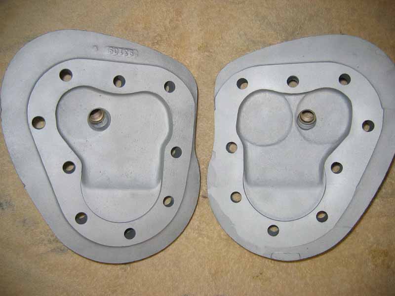
The heads shown above are both from my Twin-Scout, but the head on the right is my earlier "small bore" version, and the head on the left is being used now in my larger "big bore" motors (.100" over-bore). On the newer head on the left, I added more filling on the sides between the valves, and the bore. There were some hollow spaces, that weren't serving any purpose. You can see the special domed fly-cut for my 1/2" tall piston domes. The domed fly-cut opens up a huge path for incoming gases to enter the bores. It seems to be working well, since I am making 6 times the power of a stock motor! You can see here, that I have filled the area at the top, between the valves. This helps swirl, and limits intake air/fuel from escaping out the exhaust valve during the overlap phase. The older head on the right was welded up in the areas, where I wanted it filled, then I hand-carved the shapes with my die grinders, and porting tools. The newer head on the left was first welded up, then CNC milled by Bruce Argetsinger of "Enfield Racing", then I hand finished it. I took a stock head, and filled it with Bondo, and carved it out to the shape I was looking for. Bruce then took it to get "laser scanned", so he could take the data, and CNC mill the new shape in the welded heads. It comes out fairly close, and requires some smoothing with porting tools afterwards. I like the results!
Relieving Heads - Making Valve to Head Clearance
It is common to need to "Relieve" the combustion chambers in the heads where the valve heads might hit the roof of the combustion chambers. Any time that hi-lift cams are installed, this clearance MUST be checked. The fuel tanks, and heads must first be removed. I like to glass-bead the chambers first, and clean them out very well with hot "Tide", and compressed air. The valves should be adjusted as normal with .004" Intake, and .006" exhaust clearance. I like to use a dial indicator on top of each valve to see exactly when they are at the maximum lift. Note: At this time, using the dial indicator, and zero'd at the top of valve lift, you can also check for the valve springs net clearance before "Coil-Bind". The minimum is .010" clearance per coil-wind of a spring. With Gary Stark's new special 7-coil springs, there should be lots of extra clearance, but with any other spring, this clearance should be checked. Using two large screwdrivers (one under each opposite side of the valve head), pry the valve upward all that it will go until it stops, and check the dial indicator to see how much extra the valve opened beyond the normal max-lift setting. Look at my "Tech Talk" section on "Valve Spring Coil-Bind"! Now, after that test is done, you check each valve one at a time for hitting the head. I like to bring the valve to it's max-lift position, and leave it there until you are ready to do the next valve. I take a big black "Magic Marker", and completely blacken the area above the valve in question. Then WITHOUT a head gasket, loosely mount the head with (3) head bolts. DO NOT tighten the bolts. They are used as a guide to locate the head above the valves. Check for any "daylight" clearance between the cylinder, and the head. If there is none, then you don't need to do any "Relieving". If there is "daylight", then you will need to die-grind some material away where the valve, and head contact. Wiggle the head around, and the valve head will leave "witness marks" in the black ink in the chamber. It will show you exactly where the valve is hitting. Be very careful to sculpt away the needed clearance. Remember, you can't put metal back, and too much metal gone will lower compression. Once you have clearanced for each valve, the head gasket thickness will provide the necessary valve to chamber clearance.
The head on the left is not yet "Relieved". The head on the right has been highly relieved for .486" lift cams, and this head has been milled ALOT! Notice how I smoothed the edge where the chamber rounds over above the cylinder. These are on my "Super Chief" 80" motor.
Fly Cutting Heads and Squish Area
As I mentioned before, the factory offered taller pistons in their "Bonneville" models, which necessitated flycutting metal out of the heads above the bores for piston clearance. Part of this process requires calculating the "Squish" area above the piston top at TDC. I have found .045"-.050" to be a safe distance between the piston top, and the head surface. Any closer, and you will hear some piston noise (I assume detonation?). It is also common knowledge, that at high RPM's, the piston top will get closer to the head from rod stretch, crank flex, etc. When I build a custom race motor, with tall pop-up forged pistons, I first measure how much the pop-up is above the cylinder deck, and then I fly-cut mill that same amount out of the head. Then I use a .050" thick copper head gasket to create the .050" squish height. The same goes for making an 80" motor out of a 74"er. There is no fly-cut in the 74" heads (unless it is a set of 74" Bonneville heads). The Chief Bonneville heads are flu-cut about .100" deep, and must be fly-cut out to around .150" for an 80" job. Always measure the pop-up height before cutting thr heads!
Gaskets
I like the stock style composite sandwich type gaskets for most street Indians, because they seal well for a long time, especially when using heads, and cylinders without a perfectly flat surface. But, for racing, I prefer the copper gaskets (.050" thick), because they come off easily, and will clean-up with some lacquer thinner. Alot of racers that use copper gaskets will clean them, and then coat each side with 2 thin coats of silver engine enamel. This helps the sealing, and cleans up well with lacquer thinner during quick servicing, while racing. The copper head gaskets will also help the heat in the heads to migrate into the cylinder tops for better head cooling (not as important on a street bike). As I said before, Cometic gaskets makes my gaskets, and for around $12.00 each. Be sure to check the gasket's inside edge, so none of it over-hangs into the bore, or chamber. If it does, it can set off some pre-ignition from hot spos. Just lightly sand off any excess edge material.
Head Bolts
Most people use normal Indian head bolts, and various types of washers. But, for my race motors, and any other special motor, I prefer to make stainless steel studs, and use "ARP" 12-point grade 10 flange-nuts (9/16" wrench). With the studs, I can custom cut each stud, so it will screw all the way down, and take advantage of every thread available in the head's bolt hole. I like to cut each stud, then bevel each end on my belt sander. Then I stamp a number at the bottom of each stud, so I can make sure it goes back into the same hole every time. I take my Dremel cut-off saw, and grind a slot on the top for a screwdriver, so I can install them easily, and snug (not super-tight). For washers, I use the older Indian "beveled edge" type as used in the 1920's. I get them from Rocky Halter. I cut the studs, so there are at least 2 full threads showing above the nuts. Now, you can get a more accurate head bolt torque job by turning the nut on a stud, instead of grinding down the head's internal threads, and sometimes stripping them! I like a little oil on the nut threads before installing them. This is a far better setup than stock, and it preserves the threaded holes. I get my stainless all-thread rod from McMaster-Carr (7/16"-20).
CONTACT INFORMATION:
James R. Mosher
(505) 466-7870