An Indian Cam and Lifter Study
I am only covering cams, and lifters for pre-war, and post war Chiefs, and Scouts.
See below for pictures, and measured cam data.
Part 2: Lobe Centers, and using "Off-Set" pins for "Press-On" Lobes to achieve a desired cam lobe location.
The results found in cam timing in Part 1 (above) were found with parts that just "dropped-in", and "What you got, is what you git!", as far as cam timing is concerned. Correct cam timing is of utmost importance when getting a motor to perform at it's best. Cams can be adjusted slightly advanced from the design spec to gain a little better low-end, while sacrificing the top end power. For our purposes here, I am sticking to the normal pattern of making the opening, and closing locations as a mirror image of the other. This is sometimes referred to as a "Split Cam". This design puts the "mid-point" of the overlap cycle at Top Dead Center, and from this TDC, the lobe centers are measured to the cam's actions "mid-point" (or Lobe Center). It can be observed that most performance cam designs use a "Lobe Center" number of between 102, and 107. These are degrees of crankshaft rotation measured after TDC (for Intake), and degrees before TDC (for Exhaust). The reason that cams numbers are all taken at a lift position of .050" above the cam's base circle, is to take measurements that are away from the cam's ramp area where a small amount of lift can occur over many degrees, and this inaccuracy can be eliminated if all measurements are taken at a higher .050" of lift. This is in the real action area of the cam, where accurate opening, and closing points can be determined for purposes of finding "Lobe Centers". The actual duration of the cams can be measured from it's actual valve opening points after setting the proper valve clearance. The duration numbers are much smaller than actual, for cams measured at .050" lift, and these numbers are just used for finding the "Lobe Centers".
Virtually all cam makers use "Even Lobe Centers", (in the low-100's)!
Unlike other cams, where there are seperate lobes per cylinder allowing any placement of a "Lobe Center", the Indian uses the same (1) lobe for both Intake, as well as Exhaust, per cylinder. This leaves few options for the cam designer. I have measured that the standard lifters (when used together), can offer a 115/115 degree "Lobe Center" split, providing that the lobe is placed in the precise spot. The Bonneville lifts that move cam timing will yield a 105/105 "Lobe Center" split when the lobe is correctly placed. Using (1) standard lift, and (1) Bonn lift, the "Lobe Center" split can be at 110/110 degrees. From this, you can see that using both Bonneville lifts is an ideal 105/105 "Lobe Center" split. Indian's "Lobe Centers" will always be decided by the choice of lifts used! Scout standard lifts can yield a 116/116 "Lobe Center" split. The Bonneville Scouts used a new, more sculptured shape that was much stronger, but only the Exhaust lift was shorter. It is normally longer than the Intake lift, but is much shorter than the Intakes in the Bonneville style. This radically reduces the possible "Lobe Center" split to 102.5/102.5, which is a very good number, if the lobe can be positioned properly.
I decided to use a degree wheel, and a dial indicator to take carefull cam timing measurements from standard Scout cams, and Lifters. From here, I can plot the "lobe Centers", and figure out how many degrees to advance, or retard the lobe to get the "lobe Centers" to equal each other. I made up a custom set of Scout Racing cams using the "Hi-Lift" lobes from Mathre, using Chief gears, and modifying their dimesnions to those of Scout gears. I temporarily used "Straight" 1/4" pins to assemble the lobe to the gear, and then installed them with the Bonneville lifts. All of the measurements were taken, and after plotting the "Lobe Centers", I could see how many degrees that I needed to move the cam lobe to find my ideal "Lobe Center" split location. In my case, I had to advance both cams by 7 degrees, and this would require some "Off-Set" Pins. I made some carefull calculations, and fount that due to the different pin hole location for Chief gears, as opposed to the Scout gears, that a sideways shift of the pin of .0062" equalls (1) degree of crank rotation in either direction. This number is .0068" per degree of rotation for the Scout. By using a (4-Jaw) chuch in my lathe, I was able to make some "Off-Set" pins that are .043" off center. After installing the "Off-Set" pins, and reinstalling the cam gear into the motor, I took new measurements. I achieved a perfect 102.5/102.5 "Lobe Center" split.
Being able to move "Lobe Centers" Is a very good thing, but unfortunately, it can only be done with "Press-On" lobes! At the present time, there are e few sets of old "Hot" cam lobes floating around, and the "Ollies" are being reproduced, and are readily available. The "Ollies" are a good performance cam, especially when used with Bonneville Lifts. The "Lobe Center" come out pretty nice. Most Indian cams are running with a degree of timing error, so while there is nothing to be done with original cams, the "Press-On" lobes can be relocated to an optimum location.
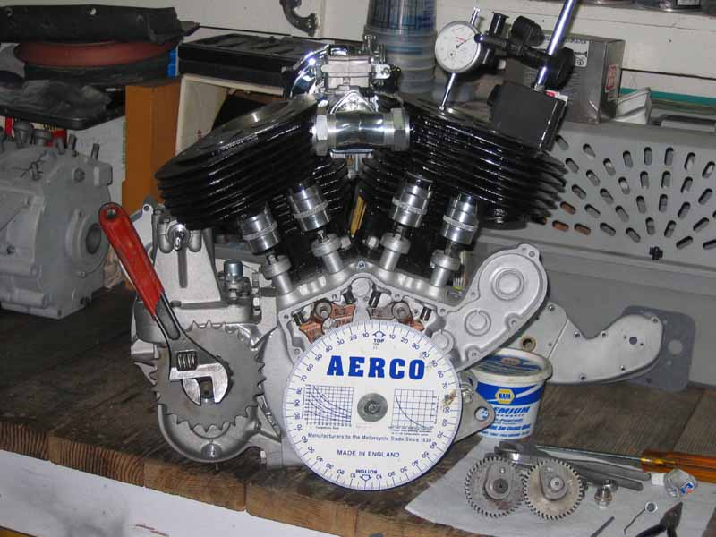
Here is my '33 Hot Rod motor using the Mathre "High Lift" Lobes with Bonneville lifts. This combo yields .485" lift, with a real 296 degrees duration. I moved the front cam lobe 7.5 degrees advanced, and the rear cam lobe 5 degrees advanced. I found a 105/105 "Lobe Center" lobe split. This cam/lifter combo now is almost identical as the very popular "Andrews-B cam" for H-D Shovelheads! These same cam lobes when used in the Scout with Bonneville Exhaust lifts yields a lesser .360" valve lift, at 296 degrees. I plan to persue getting some other style Performance "Press-On" lobes reproduced.
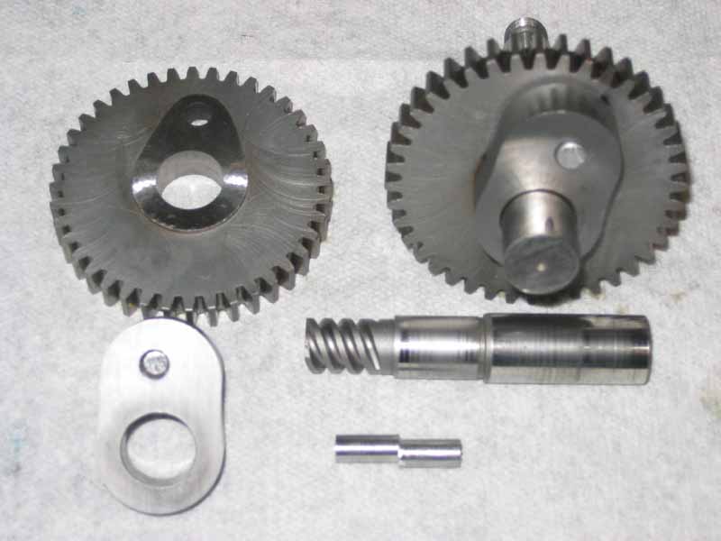
Here are the parts for my Custom Scout Racing cams. You can see the "Off-Set" pin, and the finished product.
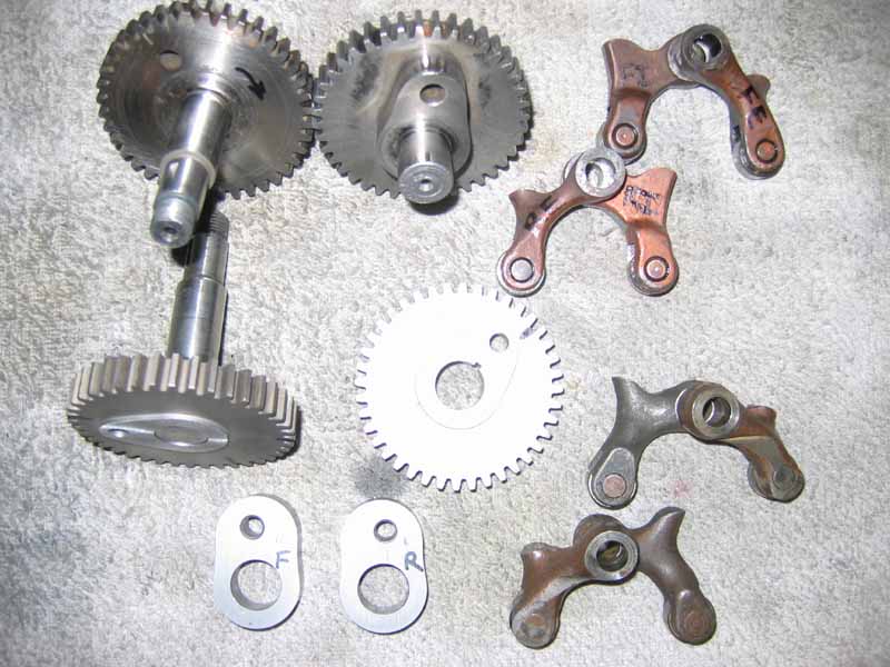
Here are standard Scout cams on top, and standard Scout lifts, also on top. Notice the shorter Exhaust lifts for the Bonneville lifts on the bottom.
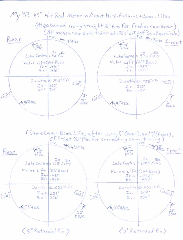
Here is a "Cam Profile" diagram of my Mathre Hi-Lift Scout Racing Cams applied to my '33 80" Hot Rod motor with Bonneville lifts. The top portion reflects measurements taken with straight 1/4" pins installed, as normal for "Press-On" lobes. The lower portion is the measurements taken after installing individual "Off-Set" pins to move the cam lobe to the position that I desire. The results are perfect "Lobe Centers" split at 105/105! The circle of the diagram represents 360 degrees of crankshaft rotation, and it takes (2) trips around the circle to complete (1) complete cycle of the (4-stroke operation). The marks inside the circle represent the Intake Valve opening, and closing points, while the marks to the outside represent the Exhaust timing points. Although, the .053" lift duration is at 256 degrees, these are actually 296 degree cams. Very Hot, and right where I want them!
CONTACT INFORMATION:
James R. Mosher
1-505-466-7870