An Indian Cam and Lifter Study
I am only covering cams, and lifters for pre-war, and post war Chiefs, and Scouts.
See below for pictures, and measured cam data.
Part 1: Lifters, and Press-On Cam Lobes.
There are (2) factory installed cam/lifter combinations that were used, Standard, and Bonneville (Note: A little known fact is that in 1948, there were optional "Sport" cams available with standard lifters, and I have a set that I have measured, and they are also featured here). Standard cams are very tame, and as you all know, they "run out of steam" fairly quickly. This is because of their short lift, and very low duration. The factory came out with the Bonneville cam/lifter set to increase power, and RPM by increasing both the lift, and duration. The factory had to change the lifter configuration to accommodate the change in cam design. They moved the rollers closer in toward the pivot shaft by nearly .085", which moves the timing by roughly 10 degrees on the new Bonneville lifters. The Bonneville Exhaust lifter will "Retard" cam timing by 10 degrees, and the Bonneville Intake lifter will "Advance" cam timing by 10 degrees as compared to the Standard lifters. By moving the rollers inward on the Bonneville lifters, the rocker-arm ratio changes from .81:1 for Standard lifters to .86:1 for Bonneville lifters. These are approximate (but very close) figures, and the variations in shape of the "humps" that contact the bottom of the push rods can slightly change these figures. Therefore, on a given cam, a Bonneville lifter not only moves the opening, and closing points by 10 degrees, it will also slightly increase valve lift compared to a Standard lifter. This description of lifters holds true for the Scout Standard, as well as Scout Bonneville lifters, except that the Scout lifters are entirely different in design, and measurements. In fact, the lifter ratios for Scouts are lower than Chief at (.62:1), which required the cam lobes to be taller in Scouts than in Chiefs. Scout cams have been observed to be more "radical" than Chiefs, but that is mostly due to appearance. They need to look "Higher-Lift" because the rocker ratio is less, and therefore, there is less valve lift achieved from the same cam lobe in a Scout than if it were installed in a Chief. People have used Scout cam lobes in Chiefs with good success. I have a set of lobes here that I have measured that have been incorrectly named "Shunk Hi-Lift" that had been sold by Charlie Mathre for years, but recently it has been revealed to me that they were a Scout performance cam with the offset pin location incorrectly placed. They appear to be very Hi-Lift, because they were intended for use in Scouts with a lower rocker-ratio. They can be used in Chiefs with alot of changes being made to the valve spring setup, as well as "relieving" metal from above the valves in the heads. In a Chief, they turn out to be the most "radical" cam available.
Some performance cam lobes have an offset pin location, where the cam lobe can be flipped over to either advance, or retard the lobe depending on how it is installed. All original Indian cams have a 1/4" hole drilled all the way through the lobe, and gear combo. I assume that it was to index the cam lobe for cutting in the gear teeth. This 1/4" hole is used to "pin" the new lobe to the gear after the original lobe is ground off. In most cases, I have measured a width of 1.125" width of the original gear, and lobe combo (.880" for Scouts). The new lobes can varry in width, so the amount of the original lobe to be ground off is exactly equal to the width of the new lobe that is going to be pressed on. Adjustments can be made to this net width to add or remove material in order to achieve the factory recommended .004" to .006" side play of the cams in the timing chest. After the cam lobes are lined up well, and pressed on, a .250" shaft (1.250" long) is pushed through the 1/4" hole, and staked over to lock the cam lobes in place. This is a very difficult job that is best left to the professionals! On some cam lobes, this 1/4" hole is centered, and therefore, a lobe can be flipped over, or used on either the front, or rear cylinders. You can't get them on wrong! These are the Bonneville, the commonly known "Ollie" lobes, and the 1948 "Sport" lobes. The next (5) sets I describe here all have pin holes offset to the side slightly. 1&2)The recently developed cams that Terry Krum provides are virtually the same lobe as an old set of lobes that I borrowed from Bob Stark's cam collection that are labeled as "Shunk 74". 3&4) I have an original set of cam lobes from Mike Breeding's collection that are stamped "Ollie" that appear to be identical to a set I borrowed from Bob Stark, but they do not appear at all similar to the modern "Ollies" that are available today. 5) The last set here are the before-mentioned "Shunk Hi-Lift" cams that were originally intended for Scouts, but the pin hole was located in the wrong place. They were drilled for a Chief cam gear, which explains the very high lift when used in a Chief. All of these (5) have offset pin holes, and weather installed on the front, or Rear cam, the lobes can be installed in their direction of rotation as advanced, or retarded. As example, the front cam as viewed from the cam lobe side rotates in a clockwise direction. With the lobe pointing upwards, the pin location should appear to be to the left of center if the lobe is desired to be advanced (to the right of center if retarded). Use some logic here! As the lobe rotates, there is a "meatier" portion of the lobe to one side of the pin location, and if it is ahead of the pin as it rotates, then the lobe is advanced. There has been alot of controversy about these offset pin locations, and their intentions. Charlie Mathre marketed his "Shunk Hi-Lift" lobes with instruction that specified that the lobes be installed in their "Retarded" position. I had long discussions with him on this, and we both are convinced that the other guy is wrong. These cams have the pin location at 9 degrees off center, so there is a difference of 18 degrees of timing (Retarded) if the lobes are installed the wrong way. Bob Stark and I had a long talk about this, and we both agree that all offset lobes should be advanced, so the intake valve will close sooner than later allowing for more compression to build on the compression stroke. Bob Stark even pulled out an original set of "Shunk" lobes where the front cam lobe was installed advanced, and the rear cam lobe was installed retarded. They were both stamped "Shunk" on their face. They might have installed a front cam lobe on the front, as well as the rear. They might have incorrectly installed the rear cam lobe, and then stamped them. Regardles, this combination was not correct in any case. Only one of the cam lobes was on correctly. Which one? I also have a set of cams that I recently removed from Mike Breeding's "Yellow Dog". They are stamped "Ollie" on both lobes, and they are in the retarded position. I have a pair of lobes from Bob Stark's collection that look identical to these in a bag labeled "Ollie", and they are stamped "F", and "R". If these were installed with "F" on the front cam, etc., they would be in the advanced position. Which way is correct? My job here is to measure the pin offsets, and then the data can be looked at and compared to known profiles for comparable applications. Idealy, in my opinion, we need to come close to the accepted figures for other popular cams, and using lobes that are retarded (as well as using Standard lifters) take us farther away from the ideal opening and closing figures. I have measured the data for these cams in their advanced state, and I am showing the pin offset in degrees. Flipping the cam lobe over will retard the same cam measurements by twice the number of offset degrees! The Shunk Hi-Lifts have a 9 degree offset ( 18 degrees if flipped, equalling (1) gear tooth), and if retarded, the intake valve won't close untill the piston is more than half way up it's compression stroke!
To identify a Standard lifter, measure the distance from the center of the roller hole to the center of the pivot shaft hole, and the distance is roughly 1.460". The Bonneville lifter will measure roughly 1.375" from center to center. On any cam, when switching over to the Bonneville lifters, the overlap increases by 20 degrees (while lobes centers move 10 degrees less), and this will significantly change the way the bike runs. In some cases, it will lower the feel of low RPM power and torque, but the higher RPM power will significantly increase. My research shows that the Standard lifters are only appropriate for Standard cams, and Bonneville lifters are the better choice for Bonneville, and ALL other aftermarket performance cams. I arrived at this conclusion by comparing various Indian performance cams measured with both Standard, and Bonneville lifter combos, and then comparing the data with known cams that have been developed for the Harley-Davidson Panhead, and Shovelhead configurations. In fact, for Indian cams with similar duration numbers to H-D cams, the Bonneville lifters get us closer to the established opening, and closing figures for the H-D performance cams. Most importantly is the closing point for the Intake valve. The Bonneville lifter advances this closing point by 10 degrees, and allows the piston to build more compression on the compression stroke. Again, we are approaching the ideal numbers found in established H-D performance grinds by using the Bonneville lifters.
I found a handy source of H-D performance cam data at ( www.nightrider.com/biketech/HDMasterCamSpecs.pdf ). All of their measurements, as well as mine, were taken at .053" lift off of the cam's base circle. This is the accepted industry standard for measurement today, and my figures can be used for comparison against other grinds.
I have found that there can be serious consequences to the valve train when using Hi-Lift performance cams (including Bonnevilles!), because of a potential "Coil-Bind" situation when using the standard valve spring with 9 coils. Please read my Valve Spring Study here for some insight, and advise.
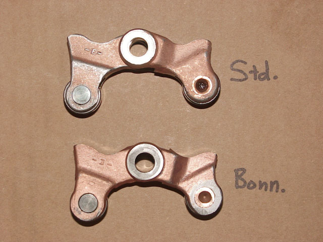
Standard Lifters on top, and Bonneville lifters below. Notice how the rollers are slightly closer to the pivot shaft holes on the Bonnevilles.
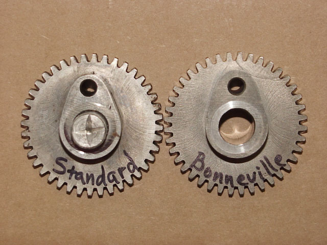
On the left is a Standard Chief cam. On the right is a Bonneville Chief cam.
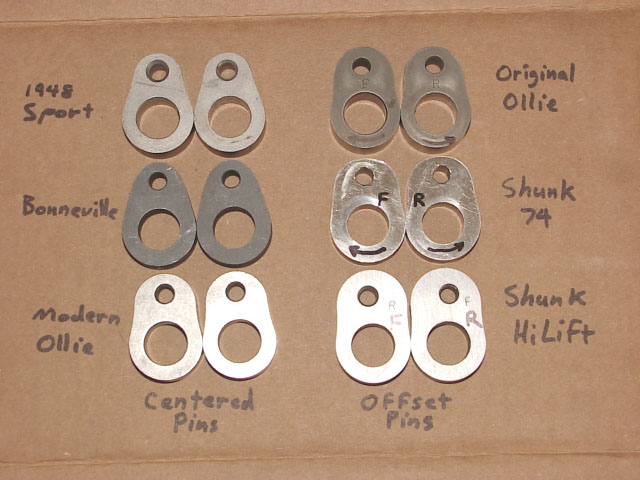
Here are (6) different performance "press-on" cam lobes. The (3) on the left have pin holes that are centered, and the (3) on the right have offset pin holes.
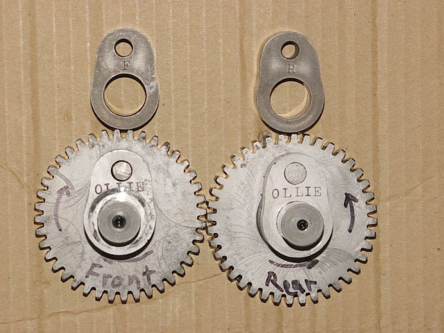
Here is an example of offset pin cam lobes that have been incorrectly installed (retarded). The lower set that are stamped Ollie are the same as the lobes above, but the lobes are stamped with an "F", and an "R". You can't put them on wrong assuming that you have the "F", and "R" showing after they are pressed on. The set that are on the gears were stamped with Ollie, but not "F&R". They probably incorrectly put the front lobe on the rear gear, etc..
Note: All of the measured data was taken at .053" lift above the cam lobe's "Base Circle". This is the standard used today!
Note: All "Offset Pin" cams were measured in their "Advanced" State. The pin "Offset" is noted in degrees, and this amount equals "One-Half" the amount the cam would be "Retarded" by, if the lobes were flipped over. Example: The Shunk 74" has a 3.5 degree offset, and if flipped over, it would retard the lobe by 7 degrees!
When comparing Indian performance cams to H-D cams, you will notice that by using Bonneville lifters, the overlap will increase by nearly 20 degrees, but the opening, and closing numbers come much closer to the desired numbers of the accepted H-D cams.
CONTACT INFORMATION:
James R. Mosher
1-505-466-7870