Indian Performance Bottom Ends
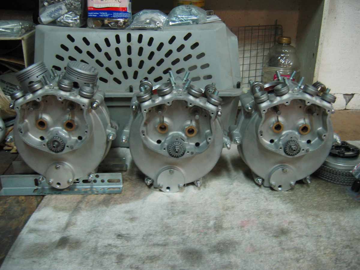
Three Scout 58" Stroker bottom ends with all the mods. Notice the '47 Chief sump scraper, and the breather hole at the top of the cases.
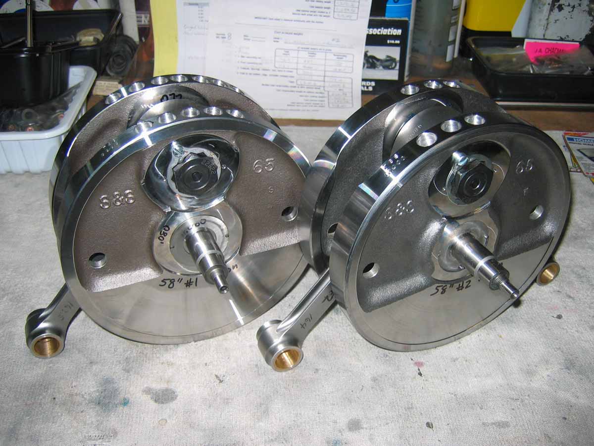
Here are the cranks for my Twin-Scout 58" Stroker motors. They are S&S light forged wheels, with Carrillo rods. Notice the balance job.
A performance bottom end for an Indian, whether Scout or Chief will differ very little compared to a street bottom end. I believe that ALL Indians will benefit from a good balance job. The method I use is a "Static Balance" using the S&S rig. They use 60% balance factor for Harley Davidsons, and they feel that 60% is also good for Indians. I have found 60% to be a good number. For very high RPM, a "Dynamic Balance" can be a better choice. The whole crank assembly (without rods) is spin balanced. I had my Twin-Scout 58" Stroker motors dynamically balanced at 62%, because it will be at max RPM most of the time. Balancing is a job best left to a professional, because there are some judgement calls needed to decide where the holes need to be drilled. When holes are drilled, it is best to drill from the rod side of the flywheel, and not to protrude through the other side! You can drill very close, but don't go through! In most cases, Chiefs will have holes drilled in the counter-weight area opposite the rod big-end. Scouts often need weight taken off the rod big-end side of the wheels. This requires very careful planning to get the weight off, without wrecking the flywheels. In any case, the very best balance job is achieved when the wheels are at their heaviest, and the rods, and pistons are at their lightest! Holes that are already there can be filled if needed by using a Mig wire welder to add the weight back, then new holes can be drilled. Carrillo rods are a very good choice. They are 2/3 the weight of a stock rod, and much stronger. Usually when a stock rod fails, they break off at the crank-pin area. I would NEVER use a stock rod in a Hot Rod Indian motor! Some people use the 80" rods, but although they are stronger with more meat at the bottom, they are much heavier than Carrillos. Spend the money on good rods, so you will never have to worry. Gary Stark is selling an exact reproduction Carrillo rod for Chiefs at good value. I use them in every motor I build.
I have built many Indian bottom ends in every possible combination, so I can add alot of experiance here. Stock flywheels are just fine, as long as they aren't beat-up. The tapers can be hogged-out if the shafts have been overtightened on past rebuilds. The cast iron is somewhat soft (including Truett & Osborne wheels), where more than 100 ft/lbs of torque on the nuts will just pull the shafts deeper into the tapers untill they spread, which just drives the shaft deeper into the taper. Always torque ALL shaft nuts to 100 ft/lbs, period! I found that a little WD-40 in the tapers, and oil on the shaft threads will allow the tapers to seat well, and show a true 100 ft/lbs on the shafts. S&S wheels are forged "Sportster Blanks", that are well made, and true fairly well. They are 15% lighter than stock, or Truett & Osborne wheels, and are best used on motors that will rev up quicker, like racers, or Bobbers with 4-speed trannys. In an 80" Chief, with heavy rods, and pistons, you will feel a jerky sensation at times, like when climbing mild hills. This will hurt the chains (primary, and drive). Keep the chains adjusted at all times! One of the problems I have seen with the S&S wheels is that the tapers need to be lubed with WD-40, so the shafts will draw in as far as possible. There is NO give to their forged material like the cast iron wheels.
Truing wheel is another job best left for a professional. First you have to have a truing stand, or at least a big lathe with some dial indicators. It is best to support the crank by the tapers in the ends of the shafts, then measure the shaft run-out as close to the wheels as possible. I call it done when I get to within .0005" run-out, and that is VERY true! Always use a lead, or copper hammer of at least 2 pounds to strike the wheels, so you don't hammer big dents in the wheels. From here it is a frustrating job getting results, and it takes experiance (like lacing spoke wheels!).
Races also need TLC. They are NOT pressed into, or out of the cases cold! First, glass bead the cases, wash them, dry them, and put them in the oven for 1 hour at 290 degrees Farenheit. This will expand the cases, and relieve tension off the races. The pinion can be carefully driven out with a light hammer, and small punch through the (2) small holes. Be patient, and gentle. Work fast before the cases cool off. Be very carefull to not hurt the inside surface of the race hole in the case. Glass bead the inside of the case race holes to clean them up. The drive race is pressed in, and out, because of a knurle towards the outside of the race. There is an oil hole inside the drive race, and it always goes upward! On a new rebuild, the drive race is removed to get the trash out of the oil groove under the small hole. I have seen cases where people in the past have ground grooves in the side of the race that runs against the flywheel thrust washers. If these grooves have a sharp edge, it will cut metal from the sides of the thrust washers like a lathe cutting tool. I have had this happen on my Twin-Scout (a very difficult repair!). The races then need to be honed on a Sunnen hone very carefully, so the roller fit is the same on all rows of rollers on the shafts. I like just a hair under .001" clearance for the pinion, and drive shafts, and just a hair over .001" for the crank pin. My Bonneville racing experiance has shown me that .001" on the crank pin is not enough (or possibly an oil delivery problem), so I use almost .0015" on the crank pins.
I have heard alot of discussion about align honing both case halves together as a unit. Assuming you are working with a factory matched set of cases, the alignment should be very close already. It wasn't untill 1948 that Indian had a through hole on the pinion race, so earlier motors need the pinion race removed, honed, and re-installed. Plus, even if you did a through hone on both races at the same time, unless you have the exact same diameter pins (pinion & drive), your clearance fit will be different per side. I never hone a race in a case, because you can't properly support the race square on the hone mandrel. Sometimes I will just touch the inside of a race on the hone after installed to fine tune the fit. It takes only a few swipes to get it just right. The older pinions can't be honed after installation, so I leave a tiny bit extra clearance when sizing it to a shaft when honing, because it will "Crush" a tiny bit when installed.
I have always had good results by removing, cleaning, honing, measuring, re-installing, and checking clearance. For those who worry about the alignment of the shafts, the first thing to worry about is the trueness of the shafts from the truing job to remove any potential wobble. Another thing to consider is that on the pinion side, there are only (2) rows of rollers next to each other, so wobble is not an issue. On the drive side the factory added a seal on the outside of the rollers in the drive race, requiring a thinner spacer between the 2nd, and 3rd row of rollers. With this narrower stack of (4) rows of rollers, any shaft wobble is less of a problem. I have seen others try to come up with a way of aligning cases with alignment pins, but I don't feel it is necessary. When I finally tighten a set of cases, I set the bare cylinders on the block's deck surface, and use them to "Square-Up" the fit by tightening all (8) base nuts in a certain sequence. When the cylinders are snugged tight, I do a final tightening on the case bolts (leave them only slightly snugged while squaring up the cases with the cylinders).
Thrust washers can also be frustrating. They have to sit very square in their recesses, and not be sloppy at the (2) small pins. This takes carefull inspection, and hand work. You don't want sloppy thrust washers, and staking them in with a punch is NOT a good fix for a loose fit. Get another thrust washer, and start over! I like to see .013" clearance between the male rod race, and either side of the female rod race. They must be absolutely square, and checked with a feeler guage at 4 corners. I like to see at least .018" (not more than .020") clearance between the flywheel's outer thrust washers, and the drive race for Scouts. Chiefs should be at .020", since they use an outboard thrust washer that sets the net clearance of the drive side, and I like .007"-.008" before fitting the outside cork washer. I always use the '52-'53 80" style seal setup on the outer drive side on every motor I build.
The cam chest area needs inspecting, and some mods. The lifter pivot shafts need to be perfect, or the lifters will rock (not good!). Replace when needed, and make sure the lifter pin bushings in the case have a .002" fit (with the pin already in the bushing). Hone the push rod guides to fit new oversized push rods to a .0015" clearance. Check the cam shaft clearance in the bushings. I always use new cam shafts, at .001" clearance. It requires special piloted reamers to ream a pair of cam bushings at a time. This is another job for a professional. Drill (4) 1/8" oil pressure feed holes in the right case just under the intersection where the lifter's arched pad meets it's push rod with the lifter resting on the cam's heel. In a Scout, when using very high lift cams (above .390" lift), the bottom of the rear cylinder's push rod guides need to be clearanced, so the lifters won't hit at high lifts (check closely, and leave at least .030" clearance). Also the pinion boss aluminum may need to be just trimmed a bit for cam lobe clearance (again, about .030" clearance).
Last of all, paint the inside of the cases with "Glyptol" red enamal (not the joint surface), inspect the cases everywhere for damage (repair first!), check the oil drain holes. Before re-installing the drive race, grind a "V" shaped trough at the oil feed hole, so it can grab a litte more oil to run into the drive race oil feed hole. On Scouts I like to drill, and tap a 1/8" NPT pipe thread on the flat "D" shaped surface of the right side case just behind the distributor for another breather port. It can be plugged off if not used. Do this before assembling the cases! I like to replace the cylinder studs with longer studs that can be bought at NAPA stores (Dorman 675-003). I clean-out the stud holes in the cases, and run down a "Bottoming Tap" so I can get a couple more threads. Then I custom cut the stud lengths to get every thread, and cut the height so that at least (2) threads of the studs extend above the base nut with washer installed on the cylinders. Also, if you are going to modify the cases to accept the 1947 style sump scraper, now is a good time to do so! I use Yamabond, or ThreeBond 1194 liquid gasket to seal the cases. Smear a very thin even coat on both surfaces, and quickly assemble the cases. Once they have joined, do not break the joint apart!
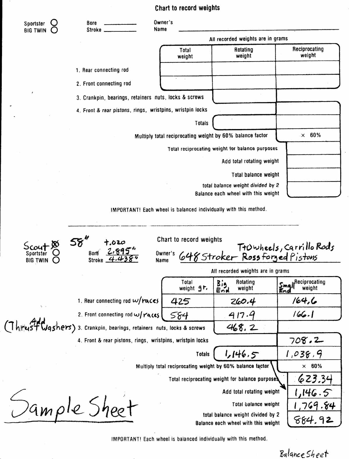
Here is an S&S balance sheet filled out for Dick Chance's Bonneville record holding Scout motor. The calculated "Bob Weight" is added to the crank pin hole of each wheel, and balanced one wheel at a time.
CONTACT INFORMATION:
James R. Mosher
(505) 466-7870